- 您现在的位置:买卖IC网 > Sheet目录99 > NHD-0220FZ-FSW-GBW-P-3V3 (Newhaven Display Intl)LCD MOD CHAR 2X20 TRANSFL
[4]?
?
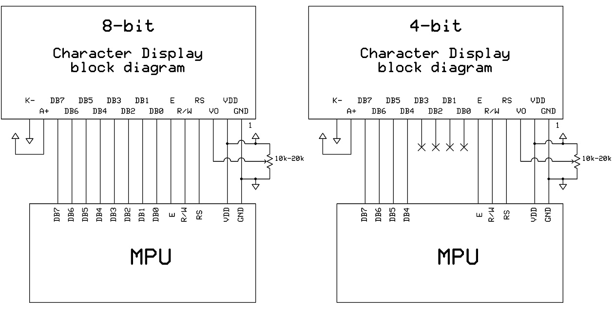
Pin?Description?and?Wiring?Diagram?
Pin?No.?
Symbol?
External?
Connection?
Function?Description
1?
VSS?
Power?Supply?
Ground
2?
VDD??Power?Supply?
Supply?Voltage?for?logic?(+3.3V)
3?
V0?
Adj?Power?Supply?
Power?supply?for?contrast?(approx.?0.3V)
4?
RS?
MPU?
Register?select?signal.?RS=0:?Command,
RS=1:?Data?
5?
R/W?
MPU?
Read/Write?select?signal,?R/W=1:?Read
R/W:?=0:?Write??
6?
E?
MPU?
Operation?enable?signal.
Falling?edge?triggered.?
7‐10?
DB0?–?DB3?
MPU?
Four?low?order?bi‐directional?three‐state?data?bus?lines.??These?four?
are?not?used?during?4‐bit?operation.?
11‐14?
DB4?–?DB7?
MPU?
Four?high?order?bi‐directional?three‐state?data?bus?lines.??
15?
LED+?
Power?Supply?
Power?supply?for?LED?Backlight?(+3.3V)
16?
LED‐?
Power?Supply?
Ground?for?Backlight
?
Recommended?LCD?connector:?1.27mm?pitch?pins?
Backlight?connector:??‐‐‐??????????Mates?with:???‐‐‐?
?
?
?
?
?

发布紧急采购,3分钟左右您将得到回复。
相关PDF资料
NHD-0220FZ-FSW-GBW-P
LCD MOD CHAR 2X20 WHI TRANSFL
NHD-0220FZ-SYG-GBW
LCD MOD CHAR 2X20 Y/G TRANSFL
NHD-0220GZ-FL-GBW
LCD MOD CHAR 2X20 Y/G TRANSFL
NHD-0220GZ-FL-YBW
LCD MOD CHAR 2X20 Y/G TRANSFL
NHD-0220GZ-FSW-GBW-LE-E
LCD MOD CHAR 2X20 EURO FONT
NHD-0220GZ-FSW-GBW-L
LCD MOD CHAR 2X20 WHITE TRANSFL
NHD-0220JZ-FL-GBW
LCD MOD CHAR 2X20 Y/G TRANSFL
NHD-0220JZ-FSB-GBW
LCD MOD CHAR 2X20 TRANSFL
相关代理商/技术参数
NHD-0220FZ-SYG-GBW
功能描述:LCD字符显示模块与配件 2 x 20 STN-GRAY 65.0 x 20.0 RoHS:否 制造商:Lumex 显示模式:Transflective 字符计数 x 行:16 x 2 特点: 流体类型:STN 接口: 背景色: 工作温度范围:- 20 C to + 70 C 封装:Bulk
NHD-0220GZ-FL-GBW
功能描述:LCD字符显示模块与配件 STN- GRAY Transfl 80.0 x 36.0 RoHS:否 制造商:Lumex 显示模式:Transflective 字符计数 x 行:16 x 2 特点: 流体类型:STN 接口: 背景色: 工作温度范围:- 20 C to + 70 C 封装:Bulk
NHD-0220GZ-FL-YBW
功能描述:LCD字符显示模块与配件 2 x 20 STN-Y/G 80.0 x 36.0 RoHS:否 制造商:Lumex 显示模式:Transflective 字符计数 x 行:16 x 2 特点: 流体类型:STN 接口: 背景色: 工作温度范围:- 20 C to + 70 C 封装:Bulk
NHD-0220GZ-FSW-GBW-L
功能描述:LCD字符显示模块与配件 STN- GRAY Transfl 80.0 x 36.0 RoHS:否 制造商:Lumex 显示模式:Transflective 字符计数 x 行:16 x 2 特点: 流体类型:STN 接口: 背景色: 工作温度范围:- 20 C to + 70 C 封装:Bulk
NHD-0220GZ-FSW-GBW-LE-E
功能描述:LCD字符显示模块与配件 STN-Gray 2x20 Transf w/ Euro Font RoHS:否 制造商:Lumex 显示模式:Transflective 字符计数 x 行:16 x 2 特点: 流体类型:STN 接口: 背景色: 工作温度范围:- 20 C to + 70 C 封装:Bulk
NHD-0220JZ-FL-GBW
功能描述:LCD字符显示模块与配件 STN- GRAY Transfl 182.0 x 60.0 RoHS:否 制造商:Lumex 显示模式:Transflective 字符计数 x 行:16 x 2 特点: 流体类型:STN 接口: 背景色: 工作温度范围:- 20 C to + 70 C 封装:Bulk
NHD-0220JZ-FSB-GBW
功能描述:LCD字符显示模块与配件 STN- GRAY Transfl 182.0 x 60.0 RoHS:否 制造商:Lumex 显示模式:Transflective 字符计数 x 行:16 x 2 特点: 流体类型:STN 接口: 背景色: 工作温度范围:- 20 C to + 70 C 封装:Bulk
NHD-0220JZ-FSPG-GBW
功能描述:LCD字符显示模块与配件 STN- GRAY Transfl 182.0 x 60.0 RoHS:否 制造商:Lumex 显示模式:Transflective 字符计数 x 行:16 x 2 特点: 流体类型:STN 接口: 背景色: 工作温度范围:- 20 C to + 70 C 封装:Bulk
